

Please follow the safety procedures from the beginning to the end of the operation.
First, the inspection before the operation
1 Turn on the circulating cooling water.
2. Connect the power to the injection molding machine.
3. Check the temperature thermocouple plug and wiring on the cartridge (after making sure it is normal, turn the heated power switch to adjust the temperature to the material that is being plasticized). (For the specific adjustment method, refer to the corresponding part in the chapter on machine adjustment)
4. Re-adjust the counter as needed. (see computer operating instructions)
Second, start and stop the oil pump motor
2.1 Follow the steps below to adjust the selector switch before starting and stopping the pump motor.
Step 1: Turn on the power of the machine;
Step 2: Put the machine in manual state.
Step 3: Press the motor start button to start the motor;
Step 4: After pressing the motor start button again, or the emergency stop button is pressed, the injection molding machine will also stop.
2.2 Notes
(1) Before starting, ensure that the hydraulic oil level is above the neutral line.
(2) Open the security door.
(3) Disconnect any hydraulic devices (valves, filters, tubing, etc.) and do not start the pump motor.
(4) Check the direction of rotation of the oil pump for a moment.
(5) If the rotation is reversed, check that the oil pump pressure sensor is connected properly.
(6) When the oil pump is running, listen for abnormal noise.
Third, mold clamping, mold opening and travel switch
3.1 clamping operation
Step 1: Close the security door;
Step 2: Put the machine in manual state;
Step 3: Press the mold clamping button.
Step 4: Start the mold.
Note 1: In order to prevent the clamping impact, when closing the mold intermittently, please choose low speed clamping.
Note 2: According to the technical parameters of the injection molding machine, the minimum thickness of the mold is correctly determined.
3.2 mold opening operation
Step 1: Place the machine in manual state;
Step 2: Press the “Open Mode” button;
Step 3: Start the mold opening.
3.3 opening and closing stroke
The opening and closing stroke is controlled by the computer, just enter the position of the electronic ruler.
Fourth, the hydraulic ejection switch
Before adjusting, start the oil pump motor and press the “Eject” button.
The ejection action will not take place unless the computer detects an "open mold end" signal. In order to be safe, do not attempt to remove the molded part while the ejection is in progress. For the adjustment of the ejection operation of the computer injection molding machine, please refer to the adjustment of the injection molding machine in Chapter 5.
4.1 continuous ejection action
For the setting of the injection molding machine for multiple times of ejection and the setting and use characteristics of multiple vibrations, please refer to the relevant part in the chapter on machine adjustment.
4.2 ejection stroke (proximity switch or electronic ruler)
For the specific position of the travel switch or electronic ruler, please refer to the travel switch or electronic ruler distribution map.
(1) Only the computer detects the ejector retraction stop signal or position, otherwise the clamping action will not proceed (this must be noted).
(2) The ejector advance stop stroke switch or position is used to control the stroke of the ejection. When setting, the initial setting of the stroke should be as short as possible, and then adjusted a little bit until the appropriate stroke is obtained. Applying this method to adjust can avoid damage to the mold (the computer uses an electronic ruler to control the ejection stroke, and can also refer to this method).
5. Injection molding device (injection stroke or nozzle) and stroke switch
5.1 If the injection unit is to be moved forward, press the shot forward button.
Note 1: The mold should be intermittently operated before it contacts the nozzle, that is, it should stop and advance immediately after entering the front to correct the position of the travel switch. At this time, the pressure and flow rate should be low.
Note 2: When the nozzle is moving forward, do not remove the flowing resin of the nozzle with bare hands. Stop the injection molding and use the tools of the iron clip to remove it, and do not directly use the hand to operate.
5.2 If the nozzle is to be retracted, press the “Four Back” button.
5.3 Injection unit stroke switch
The jet forward travel switch operates when the nozzle contacts the mold. When automatic, unless the switch is activated, the injection will not proceed and the cycle will be aborted.
Six, install the mold
6.1 Before installing the mold
(1) Please refer to the mold adaptation drawing in Chapter 8 to ensure that the selected mold is suitable for the specifications of the injection molding machine.
(2) If the positioning ring is mounted on the mold, the nozzle centering point is very simple when the mold is installed.
(3) Adjust the mechanical protection safety device, the thimble stroke and the limit switch on the mold clamping side, etc., so as not to damage the mold when adjusting the thickness of the mold.
(4) Prepare assembly bolts, connectors, tools, etc.
6.2 Molding (all manual control)
Step 1: When the movable template is not in the mold opening stop position.
(1) starting the oil pump motor;
(2) opening the mold to open the mold;
(3) moving the nozzle backward;
(4) Turn off the oil pump motor.
Step 2: Adjust the position of the thimble to fit the mold.
Step 3: Open the mode adjustment function key.
Note: The type and method of use of the switch varies with the control system. You can also press the mold switch after step 11 of the mold.
Step 4: Lift the pair of mold lobes, pay attention to the position of the locating ring holes, etc., and temporarily position them on the fixed stencil.
Note: When lifting, it should be determined that the mold lobes will not be separated. For the bolt size, see the mold fit diagram. The screw's screw depth H should be 1.5~1.8 times the bolt diameter φD.
Step 5: Start the oil pump motor.
Step 6: Press the “Clamp” button intermittently and the mold is gradually closed.
Step 7: After the mold is completely closed, perform the nozzle contact operation to ensure that the nozzle contacts the mold accurately. Before the actual contact, press the “stage advance” button intermittently until the nozzle touches the center of the mold. If it is not centered, it can be adjusted up and down and left and right as needed.
Step 8: Turn off the oil pump motor.
Step 9: Tighten the bolts that secure the mold to the stationary and active stencils.
Note: The mold must be securely positioned so that the mold does not fall when the mold is unlocked. However, it is not possible to apply excessive torque to the die screw to prevent the screw holes on the template from slipping.
Step 10: Remove the belt or steel cord used for lifting.
Step 11: Start the oil pump motor.
Step 12: Open the “Module Modification” button and start manual mode adjustment.
Step 13: Set the opening and closing pressure and flow rate during mold adjustment, and the pressure and flow rate of the mold adjustment (no adjustment is required when adjusting the mold with a geared motor).
Step 14: Repeat the opening and closing of the mold so that the energy saving of the elbow is just straightened when the mold is closed, and the value of the pressure gauge is observed to adjust the appropriate clamping force.
Step 15: Press the mode adjustment function button again to end the mode adjustment.
Step 18: When the product is tested, according to the quality of the product, repeat steps 13-16 to minimize the clamping force under the premise of product qualification, which is beneficial to the service life of the machine.
If you use the automatic mode adjustment function, the basic operation is as follows:
Step 13: Open and close the mold and adjust the parameter settings.
Step 14: Close the security door and press the auto-adjust button.
Step 15: The machine will automatically adjust the mold. After the mold adjustment is completed, the machine will return to manual.
Manual control repeats clamping and mold opening, injection seat advancement and retraction, and full inspection to ensure that the mold mounting and limit switch adjustments are correct.
7. Plasticized metering, injection, anti-mite (retraction) operation of the screw
Note 1: In order to protect the screw, the screw-related action (injection, melting, loosening) should be started after the temperature of each point of the heating cylinder reaches the set temperature for 15 to 30 minutes.
Note 2: In order to prevent the screw from being damaged, the test operation should be carried out at a speed of 60 rpm or less in the case of no material idling.
Note 3: Do not put your hands and face close to the tip of the nozzle.
Note 4: Please refer to the computer operating instructions for the control position of the screw injection stroke.
7.1 Metering operation (rotation of the screw)
When the melt button is pressed, the screw rotates and gradually retracts to the stop (pre-plastic stop) metering position and stops. You can also press the melt button again to stop the screw.
7.2 Press the “shot glue” button and the injection action will begin.
7.3 screw anti-mite.
Press the "Retract" button and the screw will begin to return.
Eight, automatic operation
8.1 Check the following 1 to 7 before starting the automatic operation.
1 Check that the operator and surrounding machines meet safety requirements.
2 Check that each safety device is functioning properly.
3 Make sure that the position of the limited position switch is correct or the position of the electronic scale is set correctly.
4 Check the timer settings.
5 Check that the pressure and flow adjustment of each action are correct.
6 Check the correctness of each action mode (automatic cycle mode).
7 Make sure that the temperature of the heated barrel is suitable for the resin being processed.
Each of the above items is inspected by starting the injection molding machine in accordance with the above 2 to 7 manual controls.
8.2 automatic operation
1 Start the oil pump motor. (Refer to the start and stop procedures of the oil pump motor in Chapter 4)
2 Make sure that the temperature of the heated barrel is suitable for the resin being processed.
3 Close the security door.
4 Turn on the automatic operation mode.
5 Switch the front safety door once or press the “locking button” (clamping, injection cycle starts).
Nine, the work is completed (close the stop device)
9.1 is just before the molding is completed or before the temporary stop.
1 Press the barrel heater to the electric “off” position.
If it is a temporary short-term shutdown, do not disconnect the heater power supply, you can heat the barrel to the "insulation" mode.
2 Close the hopper baffle.
9.2 When the material is used up or the number of required products has been molded and the electric shutdown must be turned off.
Not only to heat the barrel in the shortest possible time during the next operation, but also to prevent the melted resin from staying in the barrel for a long time, the residual material in the heating cylinder should be completely removed.
(Because plasticized materials may explode, care must be taken to avoid burning when cleaning.)
9.3 Manual control, mold clamping (the mold just touched, there is no high pressure), and the injection seat and screw are returned to the stop position.
9.4 Shut down the oil pump motor, press the emergency stop button, and also disconnect the total power supply of the injection molding machine.
4.9.5 Change color or refueling.
9.5.1 Thoroughly clean the barrel.
9.5.2 Refueling or changing colors will depend on the type of material used. After reducing the plasticizing temperature of the heating cylinder, then change the color or refuel.
Ten, unloading the mold (completely under manual control)
Step 1: Start the oil pump motor.
Step 2: Close the mold completely.
Step 3: Shut down the oil pump motor.
Step 4: Open the safety door, install the bolt on the mold, and put on the steel rope for lifting.
Note: When the injection molding machine is turned on, make sure that the two lobes of the mold are not separated.
Step 5: Remove all clamps from the mold.
Step 6: Start the oil pump motor.
Step 7: Press the “Open Mode” button to open the mold.
Step 8: When the mold opening operation is completed, shut off the oil pump motor.
Step 9: Lift the mold out of the injection molding machine and place it in the right place.
XI. Unloading the screw and heating the barrel
1 Reassemble, follow the reverse steps of disassembly and arrange the parts accordingly.
2 If the bolt of the nozzle flange is tightened too tightly, it may cause damage to the thread, but if it is too loose, it may leak. (For the convenience of disassembling the nozzle flange, please apply gold oil when screwing on the screw.) Tighten the flange bolts of the nozzle flange, please proceed in the order shown.
(1) Tighten the diagonal bolts evenly, each time several times.
(2) Use the appropriate torque.
(3) Finally tighten all bolts.
11.1.1 Before disassembly
Since polycarbonate and hard polyvinyl chloride and the like are highly viscous, they tend to stick to the screw and the heating barrel upon cooling. Especially polycarbonates, if they are peeled off, they can damage the metal surface. If these resins are used, they should be cleaned with polystyrene, polyethylene or cleaning material to simplify the cleaning and disassembly of the screw. (refers to the injection of polystyrene, etc. several times)
11.1.2 Materials to be prepared in addition to tools:
(1) 4 or 5 wood or steel rods (diameter < diameter of the screw) × (length < injection stroke>).
(2) 4 or 5 square wood poles (100mm × 300mm)
(3) Fixture.
(4) Waste cotton wool or rags.
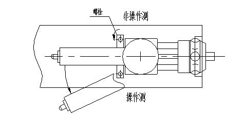
11.2 Move the injection unit to the side.
11.2.1 Use the selector switch of the injection unit to retract the injection unit until it stops.
11.2.2 Remove the bolt that stops the sliding of the injection unit.
11.2.3 Loosen the adjusting screw that adjusts the height of the nozzle completely.
11.2.4 Push the front end of the heating cylinder from the non-operating side to the operating side, taking care not to over-tighten the wires and hoses.
11.3 Disassembly
11.3.1 Disconnect the heater from the heater by heating the temperature of the heated barrel to a value close to the maximum value of the resin used.
11.3.2 Reduce the injection speed and injection pressure.
For injection molding machines capable of controlling injection speed and pressure in multiple stages, all injection speeds and pressures are adjusted to approximately 50%.
11.3.3 Remove the fixing ring of the screw (the number in the circle indicates the order of disassembly)
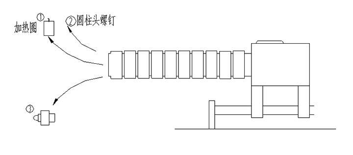
Remove the heated barrel and the end of the nozzle. When the nozzle needs cleaning, the nozzle should be removed first.
Place the screw retaining ring bolts and other bolts separately to avoid confusion.
11.3.4 Disassemble the screw (make sure the injection pressure has been lowered)
step 1:
Place a piece of wood on the end of the injection rod (see sketch) and use a clamp instead of holding the wood with your hand.
Step 2: Manually move the glue forward to move the screw while removing the clamp.
Step 3: Return after the injection screw is fully advanced.
Step 4: Put a second piece of wood on it.
Step 5: Apply the glue again and push the screw forward.
Step 6: At this time, after repeating steps 1 to 5, it is possible to remove the screw by hand.
Note: The screw may still be overheated. Do not scratch it with bare hands. Move to the left and disassemble it is very simple.
Step 7: To avoid damage to the screw, place it on a wooden block or wooden frame.
11.3.5 Removing the screw (this section is for reference)
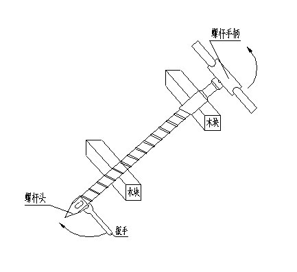
Place the screw handle on the part of the screw engraved with the keyway, clamp the screw head with a wrench, and rotate it in the direction shown in the sketch to disengage it from the screw. Note that the screw head is a left-handed thread.
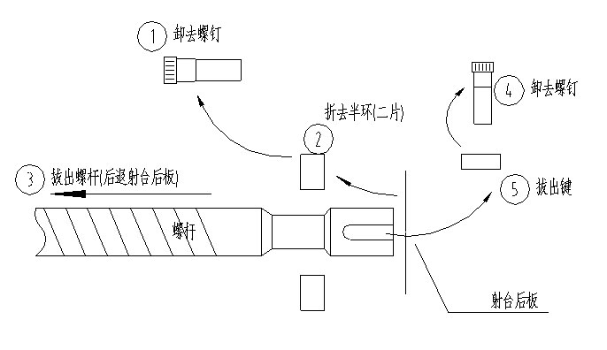
11.3.6 Disassemble the heating barrel
When disassembling the heating barrel and the screw, first remove the screw and then remove the barrel.
Step 1: Remove all the electric heating coils of the heating barrel.
Step 2: Remove the nut that holds the barrel.
Step 3: Temporarily suspend the barrel as shown.
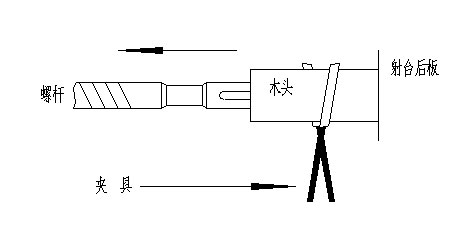
Step 4: Insert the wood between the screw and the heating barrel as shown in the figure. Don't forget to use the clamp to clamp the wood. It is dangerous to use only the hand.
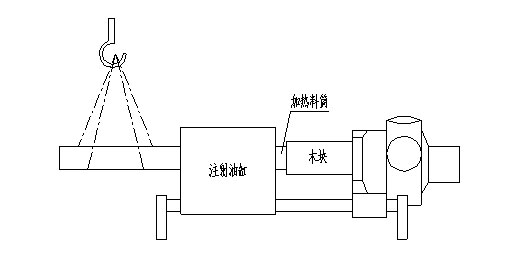
Step 5: Ensure that the injection speed and pressure are reduced, then perform the screw injection and screw retraction operation as soon as possible to advance the screw. When the wood rod is fully inserted between the heating barrel and the screw, remove the iron clip from the wood rod.
Step 6: After the screw has moved forward all the way, it is retracted, another second wood is placed, and then moved forward again.
Step 7: After about half of the length of the heating barrel has been pushed out of the injection head plate, lower the heating cylinder to a level.
Step 8: Repeat steps 4 through 7 and finally push the barrel out.
Step 9: After the heating cartridge has been removed, it should be placed in a place where the next step of work is not disturbed.
 Website QR code
COPYRIGHT:Guangdong Hang Sang Machinery Co., Ltd. Powered by:11400.cc